
Follow up: see Aug. 19, 2019 blog post.
I took a look at several documents that were emailed to me, at my request, on March 21, 2018: the “Building Envelope and Structural Conditions Assessment” for Sibley Hall at Cornell University (prepared by Ryan-Biggs Associates in May 2009) as well as four pages of structural plans and details for the third-floor renovation of E. Sibley Hall (prepared by Robert Silman Associates in March 2015). It seems to me that the structural analysis and mitigation measures proposed for the E. Sibley roof do not reflect the actual behavior of the roof members and do not explain observed displacements, misalignments, and rotations of columns, attic joists, girders, and roof rafters. I am not a structural engineer, but I think that the discrepancies between the Assessment report and structural analysis, on the one hand, and the observed conditions in E. SIbley Hall, on the other hand, warrant further investigation.
First, there is no mention anywhere, in any of the documents, of second-floor and especially third-floor column misalignment, attic joist displacement and rotation, and girder bowing in E. SIbley Hall. Either the engineers simply missed these important structural conditions in their site investigations, or the misalignments, displacements, rotations, and so on occurred after their reports and drawings were prepared — for example, they might have occurred as a result of construction during the third-floor E. Sibley renovation itself. It is also possible that these conditions occurred, or were exacerbated, as a result of the 2009 excavation for Milstein Hall and the underpinning of E. Sibley foundations, or it is possible that they occurred as a result of some original skylight installation decades ago. It would be important to know whether these structural problems (not mentioned in any of the documents) existed before the E. Sibley renovation and the Milstein Hall excavation took place. I was a student here, spending my entire freshman year on the third floor of E. Sibley Hall in 1970–1971; I don’t recall any column misalignment at that time, but, of course, I may not have noticed. I also can’t find any early photos of the interior of E. Sibley Hall that might allow us to determine when this misalignment happened. The two photos showing the interior of E. Sibley Hall provided in the Assessment report are inconclusive, but perhaps the engineers took other photos (not in their Assessment report) that might show the condition of the columns in 2008.
Second, the Assessment report repeatedly emphasizes and notes an outward movement of the exterior masonry walls in E. Sibley Hall. Such an outward movement does not explain (and in fact appears to contradict) the observed inward movement of the interior wooden columns on the third floor of E. Sibley Hall where the skylight opening occurs. This alleged outward movement of the masonry walls is not visible by casual observation, and no evidence is produced to support the contention that the masonry walls have, in fact, displaced laterally. Nor is it clear, even if there has been some outward movement of the masonry walls, that this movement explains the distress in the roof structure.
Third, there is no analysis in the Assessment report or in Silman’s structural drawings of the actual structural behavior of the wooden roof elements in E. SIbley Hall, behavior that is alleged to have caused this outward “thrust” on the exterior masonry walls. In fact, the behavior of this structure is rather complex, since it contains several internal “hinges,” especially at the intersection of the lower and upper sloping members that create the Mansard form. Such hinge conditions could explain why there may well have been both an outward and an inward thrust on the exterior walls (outward) and the interior columns (inward) respectively — especially when attic joists under the skylights were removed. Silman’s structural drawings do not even represent the lower part of the Mansard structure in their “Existing Attic Framing Configuration” section (Figure 1). There is no way to fully understand the structural behavior of E. Sibley’s roof framing without including these Mansard elements in the sections and in the analysis.
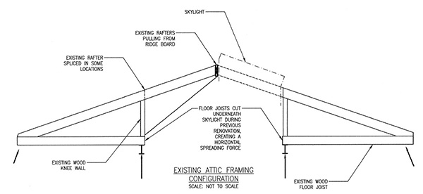
Figure 1. Existing attic framing section from Silman structural drawings, Drawing No. S-110.
Fourth, this mischaracterization of the behavior of the roof apparently led to the conclusion that the two interior lines of girders above the wooden columns on the third floor of E. Sibley Hall should be connected with cables or rods (in tension) to protect against the alleged outward thrust of the roof elements. These tension cables are clearly useless (they are slack) and, in fact, will do nothing to protect against a mode of failure in which the girders above the two lines of inner columns, already leaning towards each other, move further inward under the roof loads (see Figure 4). Silman’s “Design Intent Narrative” is based entirely on the premise of adding tension rods between the third-floor girders to “resolve horizontal spreading force.” There is no mention of the observed fact that, rather than “spreading,” the third-floor columns, along with the girders they support, are actually leaning inward.
Fifth, there appears to be a much smaller misalignment of several second-floor columns in E. Sibley Hall, but in the opposite direction of the third floor columns. In other words, some of the second-floor columns appear to be leaning outward, while the third-floor columns appear to be leaning inward. This could be the result of some outward spreading of the exterior masonry walls. However, such spreading, to the extent that it has occurred, seems to be relatively insignificant in terms of explaining the behavior of the wooden roof structure. There is no obvious evidence of outward movement of the exterior walls from inside E. Sibley Hall. On the third floor, the top edge of the masonry wall appears perfectly straight, whereas the girders over the interior column lines are remarkably out of alignment (see Figure 2 and Figure 3).
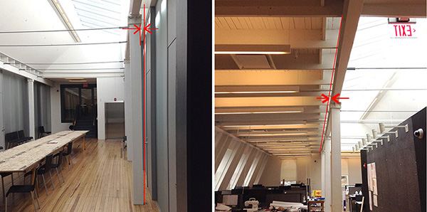
Figure 2. These images show the misalignment of third-floor columns (left) and the bowing of the steel girders that they support (right). Photos by J. Ochshorn, April 2018.
Sixth, these column/girder misalignments appear to happen only where the skylights in E. Sibley Hall occur, presumably because either attic joists were removed, or because the structure was not adequately braced during the renovation of the third floor when the older skylight frame was removed. In other words, my assumption is that these former structural elements (i.e., either the attic joists or skylight mullions in the plane of the roof) allowed the inward-acting tendencies (thrusts) of the north and south mansard sections to counteract each other in compression and thereby provide more than 100 years of equilibrium.
Seventh, Silman’s section notes that the “existing rafters [are] pulling from ridge board.” This observation actually contradicts the premise of their structural design — that the roof structure is thrusting outwards. If that premise were true, one would expect that the rafters would be in compression, pushing against the ridge board, rather than in tension, pulling away from the ridge board. This separation of the rafters from the ridge board is better explained by a rotation of the rafter-attic joist-knee wall (considered as a rigid free-body) over the girder on which it is “balanced” — facilitated by its unstable connection (hinge) to the lower inclined Mansard element. This explanation is much more plausible than the “spreading” explanation, since it is consistent with the observed rotation of these wooden roof elements and with the inward displacement of the supporting girder. I measured the distance from the bottom of the attic joists to the finished floor and found that the attic joists were indeed significantly lower where they connect with the inclined Mansard elements, but only at the locations where the columns were most displaced. As would be expected, these locations of maximum column displacement and maximum attic joist rotation occur toward the middle of the north-south bracing walls, as shown schematically in Figure 3: Attic joist “A” (at the bracing wall or frame) is horizontal, with no apparent rotation, whereas attic joist “B” shows significant rotation, with its northern end 1.5 inches lower than its southern end. This rotation, made possible by the “hinged” connection to the inclined Mansard supports, is easier to visualize by examining the section in Figure 4.

Figure 3. This is an annotated, revised, and schematic version of Silman’s “Attic Floor Existing Framing” plan, showing not only how columns and girders are displaced between the north-south bracing walls, but how the attic joist-rafter elements, considered as rigid free-bodies, have rotated and displaced laterally. Locations of maximum column displacement and maximum attic joist rotation occur toward the middle of the north-south bracing walls: Attic joist “A” (at the bracing wall or frame) is horizontal, with no apparent rotation, whereas attic joist “B” shows significant rotation, with its northern end 1.5 inches lower than its southern end. This rotation, made possible by the “hinged” connection to the inclined Mansard supports, is easier to visualize by examining the section in Figure 4. (Annotations and revisions by J. Ochshorn, April 2018)
Eighth, the inward bowing of the steel girders over the misaligned columns on the third floor of E. SIbley (Figures 2 and 3) indicates that these girders — designed to transfer the gravity loads of the roof structure to the columns — are now also acting as parabolic tension chains, resisting the further inward movement of the columns and attic joists (Figure 3). Clearly, these girders were not intended to act in this manner, and there has been no mention, in either the Assessment report or in Silman’s structural drawings, of this potentially dangerous condition. If these girders fail in tension as a result of the inward-acting lateral forces being applied to them by the rafters and attic joists of the roof structure, it is possible that a total failure of the roof structure could follow. Figure 4 shows the observed and alleged movement of columns and walls in E. Sibley Hall. This movement is consistent with a structural model of the Mansard’s wooden elements that is explicitly unstable (i.e., creating what is called a “mechanism”) because it includes an internal hinge at the top of the inclined Mansard supporting wall, making the structure underconstrained internally. It is possible that the third-floor steel girders, having been transformed into parabolic tension chains, are the only things preventing a structural collapse.
Ninth, if the tension rods were ever tightened to reduce their sag, this would have made the condition even worse.

Figure 4. This is an annotated, revised, and schematic version of the section through E. Sibley Hall provided in the Assessment Report prepared by Ryan-Biggs Associates in May 2009. The black lines show an idealized condition, with no displacement of columns, walls, or girders; the red lines and tones show the current condition (not to scale), with a small outward displacement of the exterior masonry wall (mentioned in the Assessment report, but not visible to the unaided eye), a large inward displacement of the interior wooden columns and their steel girders, and a substantial rotation and displacement of the wooden attic joists and rafters that are supported by the displaced columns/girders on one side, and by the inclined Mansard structure on the other side; and the blue dotted lines show a possible failure mechanism. The roof structure appears to be unstable in its current configuration. (Annotations and revisions by J. Ochshorn, April 2018)
I want to make it clear that I am not suggesting that the E. Sibley Hall roof structure either is, or is not, in danger of collapse. I am not competent to make such a determination. My concern is that neither the Assessment report nor the Silman structural analysis (1) acknowledges the complex nature of this potentially unstable roof structure, (2) notes the actual displaced, misaligned, and rotated condition of the third-floor structural columns, girders, attic joists, and rafters, (3) discusses the structural geometries and forces that would explain these observed conditions, and (4) proposes a remediation strategy that follows logically from an adequate structural analysis.
I strongly believe that Cornell should immediately engage the services of a consulting engineer — preferably an office that was not involved in producing the Assessment report or the structural drawings for the E. Sibley renovation — in order to assess the conditions in E. Sibley Hall and to make recommendations for remediation.
It’s just a never ending set of challenges…. who is minding the store?
one of these days I am going to have to come up and see for myself. Maybe I’ll catch a ride with Patrick (with whom I am teaching thesis this semester)- but probably not this spring…