
[Updated below: Oct. 26, 2015] The current schematic design proposal for a Fine Arts Library in Cornell University’s Rand Hall calls for hanging multiple levels of book stack floors from new transfer girders spanning from newly-reinforced columns on the building perimeter. But is it really necessary to destroy the building’s interior structure, run new transfer girders at the roof level to the building perimeter (requiring the reinforcement of exterior columns and underpinning of exterior foundations) and hang stack levels from these new roof girders? Can Rand Hall’s existing structure support library stacks on its second and third floors without going to all this expense?
Well, it’s clear that the existing floor structure is adequate for library stack loads, since library stacks have already been placed on the third floor of Rand Hall. It’s also clear that the existing second and third floor columns of Rand Hall are perfectly capable of supporting library stacks, since, on the one hand, the third-floor columns only support the roof and, on the other hand, the second-floor columns are already supporting library stack loads from the third floor.
It’s also clear that the total available floor area for a library on the existing second and third floors of Rand Hall is comparable to the floor area proposed in the schematic design submission, so that the rationale for going to all this trouble has nothing to do with increasing available floor area beyond what is currently existing.
Therefore, the only remaining practical issue that might justify a more elaborate and expensive design scheme, such as the one proposed, is whether the first-floor columns in Rand Hall could actually support the additional loads brought about by having stack areas on both the second and third floors of Rand Hall.
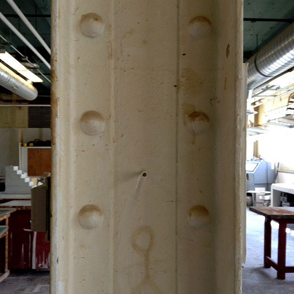
Rand Hall’s first-floor column (photo by J. Ochshorn, Aug., 2015)
Let’s find out. Disclaimer: I’m not a structural engineer, and the following preliminary calculations should, of course, be checked by a competent professional.
First, some analysis assumptions.
1. We’ll assume typical library stack live loads of 150 psf (the same number used in the proposed Rand Hall library schematic design calculations, and the number commonly found in building codes for stacks no higher than about 7.5 feet) and assume a dead load of 65 psf, which seems reasonable (this number corresponds to the weight of an average reinforced concrete slab thickness of about 5 inches).
2. We’ll assume steel properties, based on values from 1911, when Rand Hall was constructed, as follows: a yield strength, Fy, of 27.5 ksi and a modulus of elasticity, E, of 29,000 ksi. [The link was updated March 31, 2018.]
3. We’ll use a tributary area for a typical column of 15 x 15.33 = 230 square feet per floor (see typical plan).
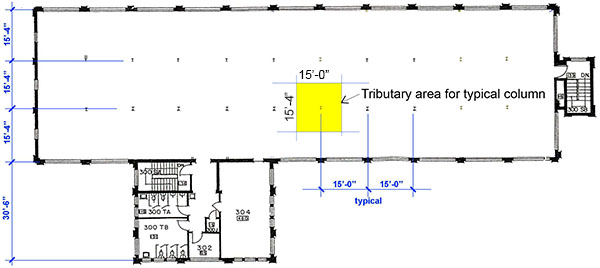
Rand Hall 3rd floor plan showing typical column tributary area
4. We’ll compute the radius of gyration for a typical first-floor column by measuring it’s cross-sectional dimensions, computing the moment of inertia about the weak axis, Iy, computing the area, A, and finding r = square root (Iy/A).
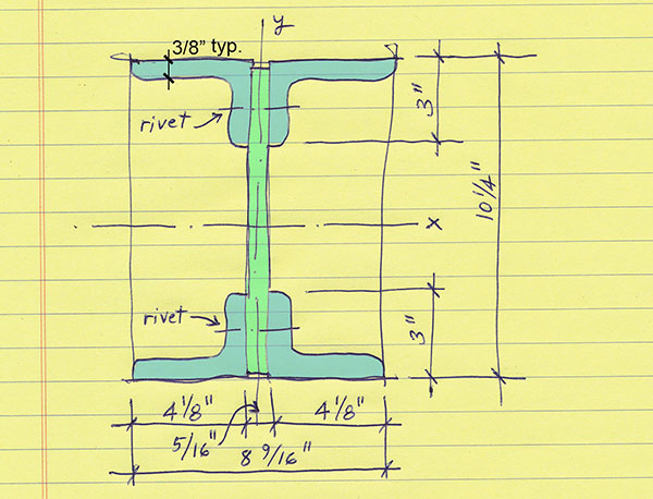
Rand Hall typical 1st-floor column cross section
Iy = (0.375 x 8.56253 / 12) x 2 + (2.625 x 1.06253 /12) x 2 + 4.25 x 0.31253 /12 = 39.77 in4
A = (0.375 x 8.5625) x 2 + (2.625 x 1.0625) x 2 + 4.25 x 0.3125 = 13.33 in2
rmin = square root (Iy / A) = square root (39.77 / 13.33) = 1.73 in.
5. We’ll assume a column height of 14 feet; so that the “nominal” (i.e., not yet accounting for the fact that the column is built-up and riveted) slenderness ratio of the column, KL/r = (1)(14×12)/1.73 = 97.1.
Next, the capacity calculations:
Because this is a built-up, riveted column section, we’ll follow the advice in the AISC Steel Construction Manual (14th edition) for built-up members (p.16.1-37) and replace the slenderness ratio, KL/r, with a modified slenderness ratio, (KL/r)m.
When the maximum distance between rivets, in this case 6 in., divided by the minimum radius of gyration of an individual component, in this case, 0.09 in. for the 5/16 in.-thick by 10 in. wide web plate, that is, 6 / 0.09 = 66.7, is greater than 40, then the modified slenderness ratio used in the capacity calculations, (KL/r)m = the square root of the sum of the squares of the nominal slenderness ratio of the whole cross section and 0.86 times the distance between connectors (i.e., 6 in.) divided by r for the web, i.e, 0.09 in; or the square root of the sum of (97.12) + (0.86 x 6 / 0.09)2 or the square root of (9428 + 3287) = 113.
There are certain dimensional requirements specified as follows: the effective slenderness ratio, Ka/ri for an individual component (in this case, governed by the steel plate web, with the fastener spacing, a = 6 in.) must be no greater than 0.75 x the nominal slenderness ratio of the whole cross section. Since (1)(6)/0.09 = 66.7 < 0.75 x 97.1 = 72.8, the sectional capacity can be based on the modified slenderness ratio found above: 113.
We need to determine whether the column behavior is elastic or inelastic by finding the slenderness ratio, called Cc, that separates these two failure modes: Cc = square root [π2 x E / 0.44Fy] = square root [π2 x 29,000 / (0.44 x 27.5)] = 154, so the column will fail inelastically. The available strength for inelastic column capacity is Fc = 0.658(Fy/Fe) x Fy / 1.67; where Fy = 27.5 ksi and Fe = π2 x E / (KL/r)m2 = π2 x 29,000 / (1132) = 22.42. Therefore:
Fc = 0.658(27.5/22.42) x 27.5 / 1.67 = 10.35 ksi.
Since the column cross-sectional area, A = 13.33 in2, the (safe) capacity of a typical first-floor column = Fc x A = 10.35 x 13.33 = 138 kips.
Finally, the maximum load acting on the first floor column is found by multiplying the tributary area for each floor by the loads acting on that floor, and taking the sum of these products:
Assuming a combined live and dead load of 150 + 65 = 215 psf for the second and third floors, and a combined snow and dead load of 40 + 65 = 105 psf for the roof, and with a tributary area per floor of 230 square feet, we get a total load of 230 x (215 + 215 + 105) = 123,050 pounds = 123 kips. Since this is less than the capacity of the column (138 kips), the Rand Hall first-floor columns are safe with library stack loads on any or all of the floors.
Updated Oct 25, 2015: At a department faculty meeting today, Dean Kent Kleinman clarified that although the steel columns can support the weight of two floors of book stacks, as demonstrated above, the underlying soil can support only one level of stacks (as is presently the case) but not two levels of stacks. According to this reasoning, the foundations would need to be somehow reinforced even for a simpler library renovation on floors two and three. However, there are other options. 1) A two-story library could be placed on the first and second floors of Rand Hall which would only put one level of stack loads on the column foundations (since there is no basement in this part of Rand Hall, one level of stacks would be supported directly on the slab-on-ground); this would allow the shop to be placed on the third floor, making exhaust ventilation easier (directly through the roof), and allowing the articulation of the existing Rand Hall facade to more clearly represent its internal functions (figure 1). This scheme also has the advantage of not requiring the shop to move to the Foundry space for more than one year, as is currently planned. The phasing of the library in its renovated spaces would also be easier to accomplish. 2) A two-story library could still be placed on the existing second and third floors, with desks or other working spaces integrated into the stack area so that overall loading is reduced on the columns.
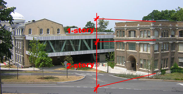
Figure 1. The existing facade of Rand Hall is articulated as a 2-story base with a 1-story top (photo by J. Ochshorn, July 19, 2012)